Assignment:
A_ Experiment with different 2D CAD tools.
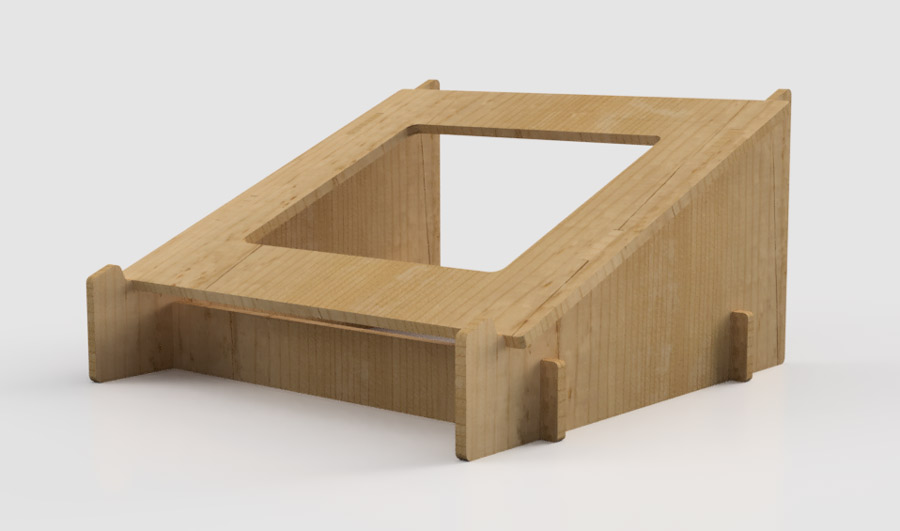
B_ Draw, model, render, animate a possible final project.
B_ Draw, model, render, animate a possible final project.
A_Experimenting with CAD tools
This week is a about learning CAD tools both for 2D and 3D applications. For 2D Cad tools I was inclined to integrate open source alternatives (Gimp and Inkscape) into my workflow. I installed them and did a few tutorials but soon realized that I would need lots of training to get conmfortable at using them. I have worked with Photophop and Illustrator for many years as an amateur and so decided to focus on training my-self to use them in a more efficient way.
Raster/vs/Vector.
I was never clear about vector/vs/raster so I studied it to get a cleared understanding. To make it simple let's say:
-Raster images are made of pixels or bitmaps and allow a wide range of colors hues that can blend into eachother. But as they are made of pixels the quality of the images depends on the amount of pixels it contains. Therefore zooming into the image makes the pixels appear and so bigger the picture more pixelated it becomes.
-Vector images are images made of paths, each with a mathematical formula (vector) that tells the path how it is shaped and what color it is bordered with or filed by. It does not let color blends and works best when there are contrasts between the colors or the tones of grey. But no matter the size it does not loose it's quality.
I learned how to convert raster image in vector image using this raster to vector tutorial. A bit funky but it explains it clearly. Here is a description of how to proceed witgh illustrator:
- open a raster image
- select Image trace/make from the object menu
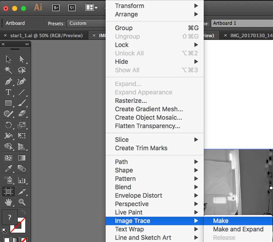
In the top tool bar select the icon that is on the right just next to the view: tracing result tab. A new window opens with different sliders allowing to tweak the image. The most important ones are the MODE (black and white, grey scale), the THREHOLD and the PATH.
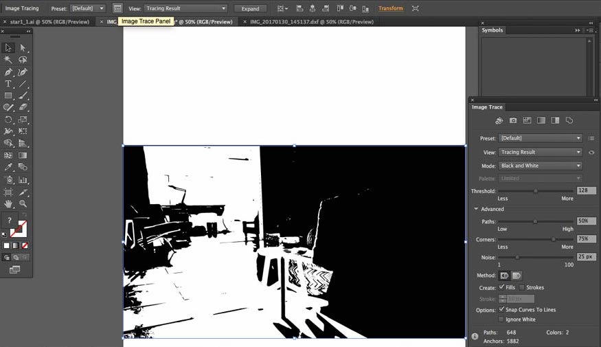
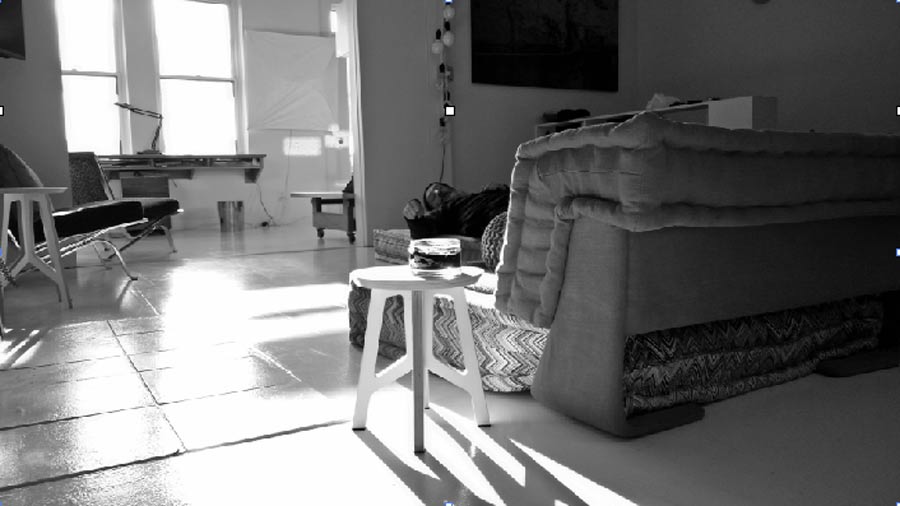
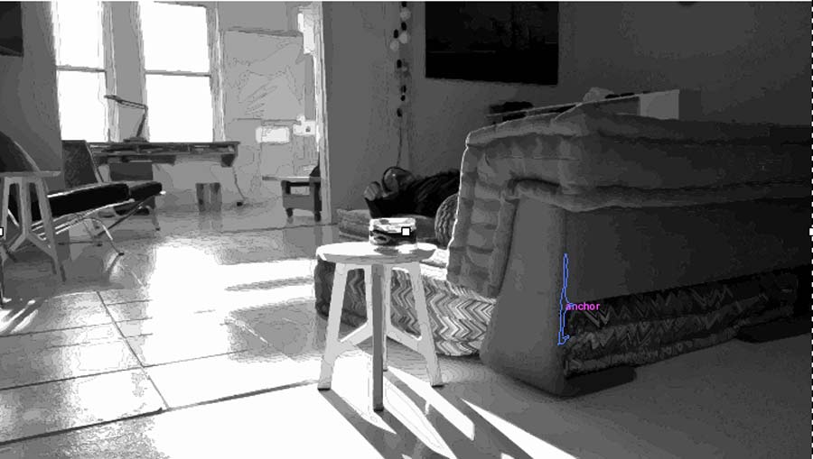
Here we can see the original raster image (left) and the conversion to vector graphic (right).
Experimenting with 3D CAD TOOLS
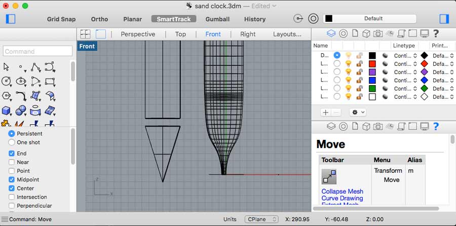
Before starting Fab Academy my only experience with 3D Cad tool was Sketchup and I used it in the past to create simple geometries and layouts but never really got very deep with it. Last year I learned some Rhino mostly in 2D modes, some 3D as well as to create Cam file for CNC milling.
After assisting to all the workshops our instructors offered on 3D CAD parametric applications (solidworks, Blender, Grasshopper and Fusion 360) I got an idea about their respective functionalities and decided which one to explore further.
Solidworks and Blender are out of the question because I work on Mac and they are supported either on pon Windows for Solidworks and on Windows and Linux fro Blender.
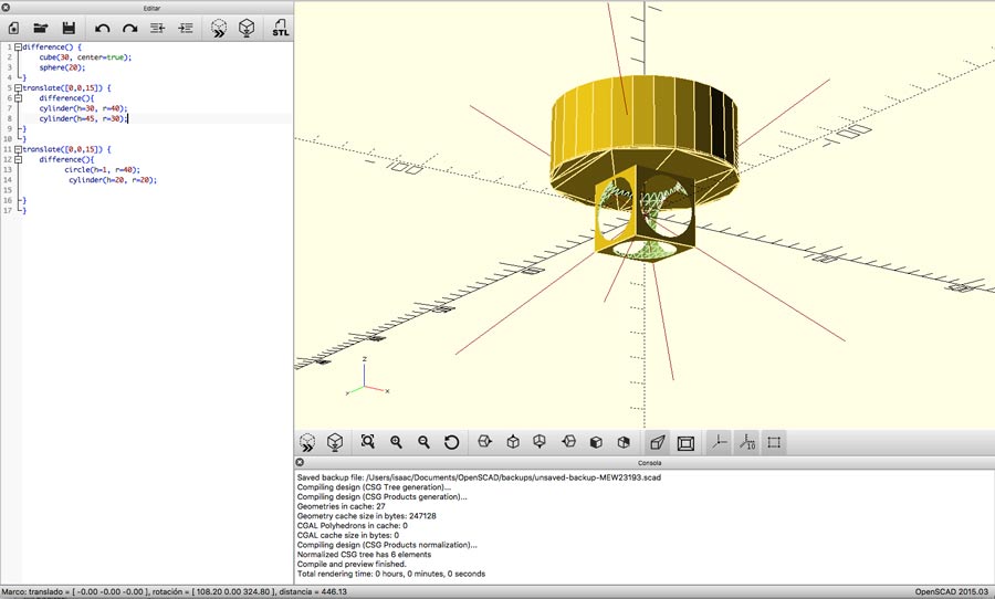
I will try Rhino + Grasshopper parametric plugins and Fusion 360 (as interfaced application)and I will try Openscad to experiment with a programmer application. Since I already have some Rhino experience, Grasshopper seems like a good option. Grasshopper is not an application but an extension (plug-in) for Rhino and runs only on the RhinoWIP version for Mac which requires a licence. There is a way around it but requires a little tweaking using terminal especially when using MacOS Sierra version. I will not document how to do that here but I can say that with a little patience and some Googling it is fairly easy.
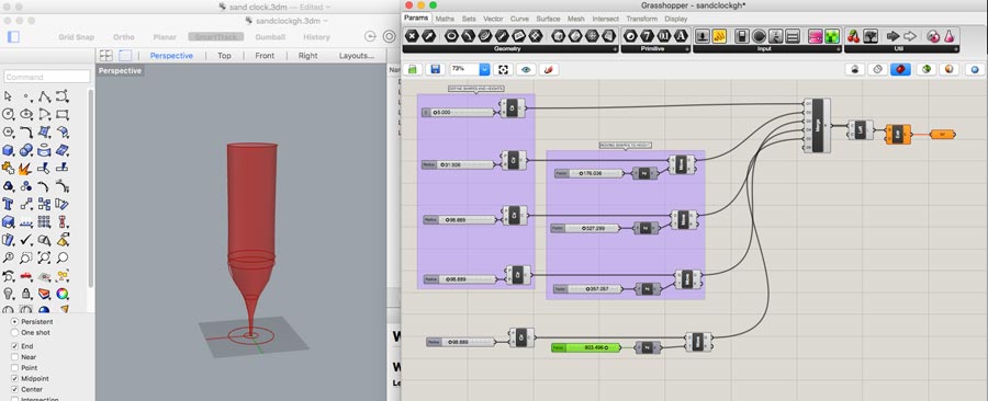
Grasshopper exercise
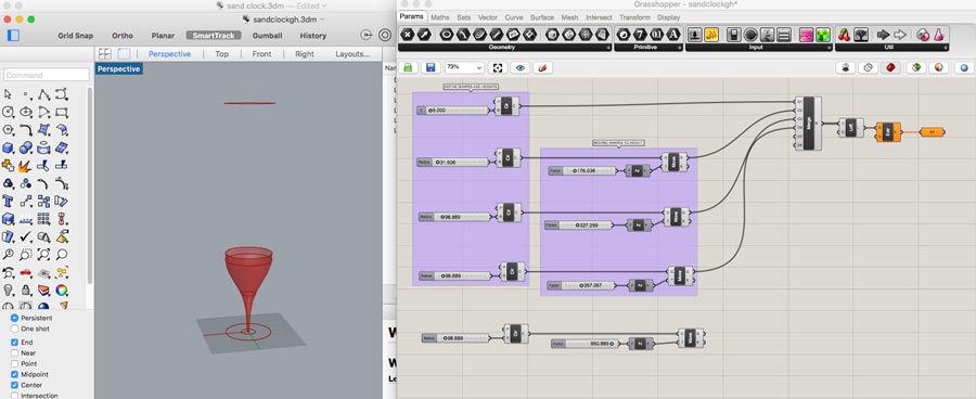
Grasshopper is a plug-in for Rhino. In Mac the RhinoWip version of Rhino Grasshopper can be launched by typing GRASSHOPPER in the command line. After watching a series of Grasshopper: getting started tutorials I went on with my first exercise of parametrizing an existing Rhino model. This got me familiar with the basic concept of parammetric design. It made me understand the importance to have a strategy when it comes down to work parametric. Staring from an existing design made it more handy for a first exercise.
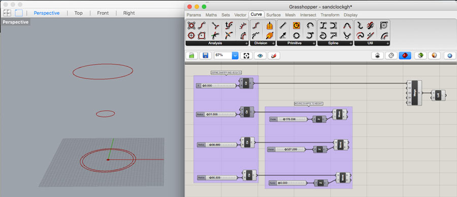
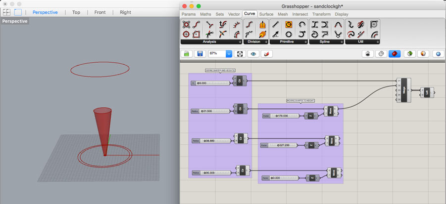
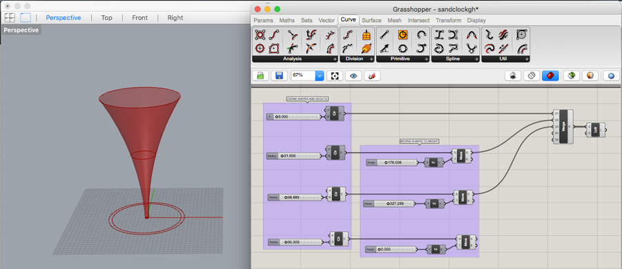
In Grasshopper, I created 4 circle nodes (from the curv family) on the default 0.
-added a number slider to each ones
-added Z axis and a move function to each circles
-merged the 4 circles
-added a loft funtion to create a solid shape.
Pressfit test for 3 and 5mm thickness material.
I continued with Grasshopper designing a simple pressfit test. My idea is to create a pressfit test that could serve any material thickness. That will be helpful as I work often with flat material and CNC. This time I started the design from scratch. Even though it is very simple design I struggled a lot to get it right.
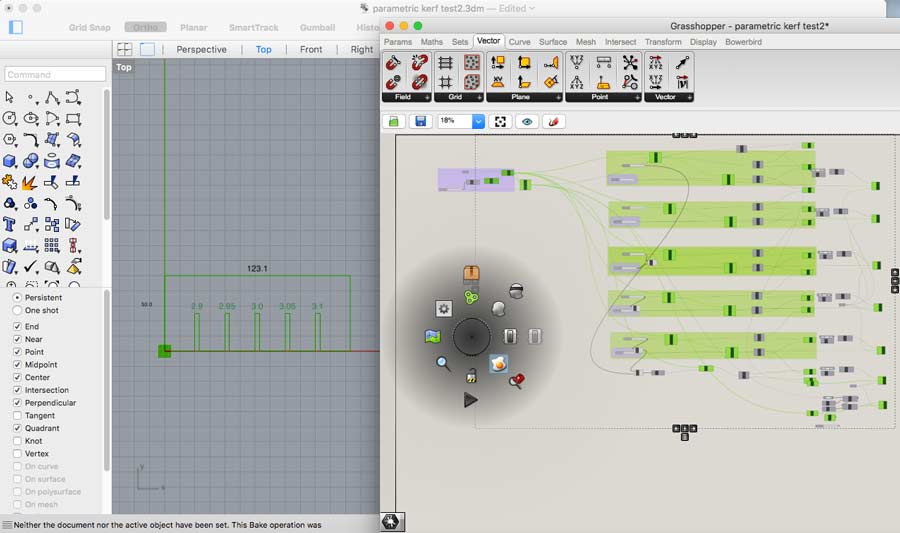
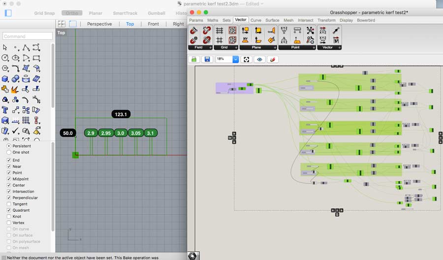
I can see how powerful Grasshopper is but it felt a bit abstract and at once too complex to handle for my skill set. I ended up spending a lot of time troubleshooting to get to perform very basic functions. That slowed down my workflow and translate into quite a bit of frustration so before going any further with Grasshopper I decided to try out Fusion 360.
Fusion 360
Fusion 360 is available for free for Students during 2 years. It can be downloaded from the Autodesk web site. Fusion 360 has the advantage of intergating a Cam file genrator within the application making it easy to create the toolpath for CNC milling in FUSION 360. This is very uselful for me as I work a lot with CNC technology. I start by watching the Fusion tutorials which helped me understand the logic and get me started. For someone new I recommend it because it introduces the logic anf functionalities of the application from the very beginning and help avoiding lots of frustration as well as learning the proper way from the start. I continued with this series of tutorials Getting started with Fusion 360
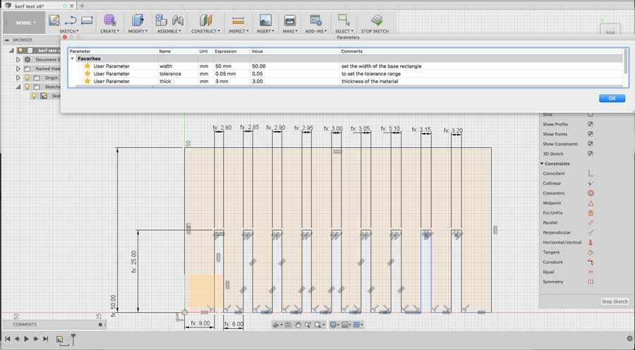
I repeated the pressfit test with Fusion 360. I taught it was going to be easy but I found my-self struggling with the constraints - especially with the combination of constraints - receiving "overconstraints" error message constantly. I looked at more tutorials and got better with using constraints.
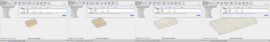
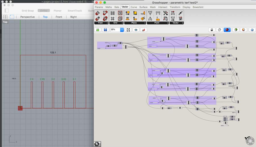
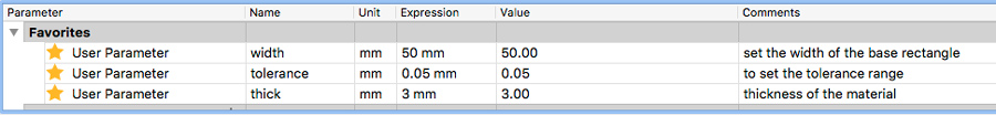
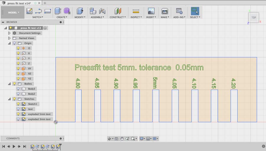
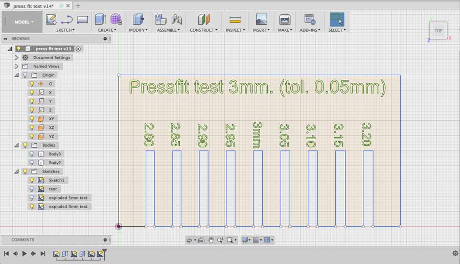
I made a sketch in which I drew lines of the profile of a rectangle that includes 9 slots. This way I can set the middle slot to the exact thickness of the material leaving 4 slots on each side for negative and and positive tolerance. For example if the material is 3mm. and I set the parameter tolerance to .05mm that would give me 2.8, 2.85,2.9, 2.95, 3, 3.05, 3.1, 3.15 and 3.2. There are 3 parameters involved :
- "width" for the height of the base rectangle.
- "tol" for tolerance.
- "thick" for material thickness.
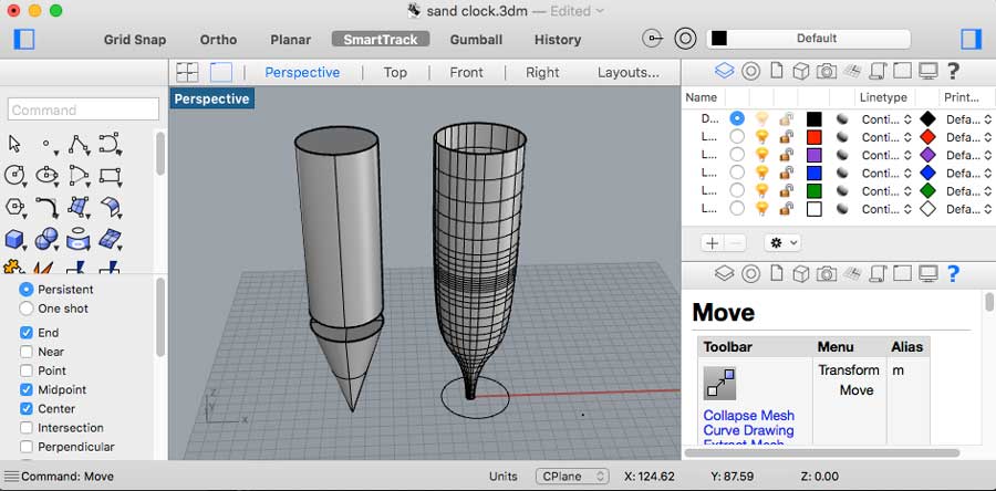
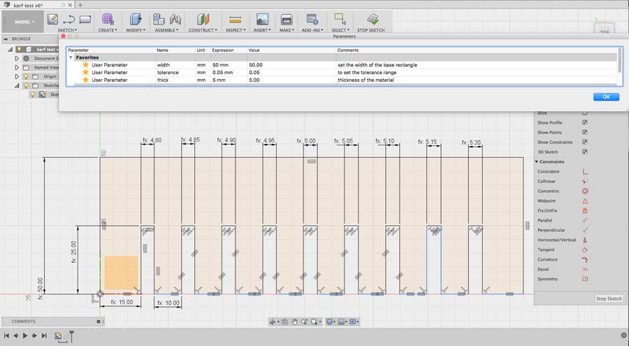
Most of the constraints I used in this design are related to the material thickness exept for the width of the base rectangle (which I set to: 2 x the lenght of the vertical slot) and an "equal" constriant for the space between the last slots and the edges of the material. The space between each slots is "2 x thick" which means 2 x material thickness. There are no "lenght" constraint so the total lenght of the base rectangle adapts automatically in lenght according to the material thickness. The following pictures show how the slots adapts when changing material thickness from 3 to 5mm.
5mm thickness
One function that I could not find in Fusion 360 and I wish would exist is one to make the measurements show as text on the DXF file. I did some research and could not found any documentation. It would be very helpful so when changing parameters the number the measurements to be printed could adapt automatically. Nevertheless I did inserted them manually creating a new sketch and inserting a title and the measurements of each slot using the sketch/text command. Then I saved each sketches in DXF format using the save as DXF function in the selected sketch tab. Surprisingly when I opened the DXF the text did not show up. It took me while and a bit of research to figure that "text" nedd to be explode before they can export as object into DXF. To do that all is needed is to select the text (drag click from left on the text), right click and select explode text. Each piece of text has to be exploded. Once I did that the text showed perfectly.
I repeated the whole process to create a pressfit test also for 3mm. thickness.
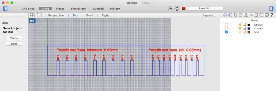
To make shure all is right I imported the dxf files in Rhino which I will use to send my file to the laser cutter. There I realized it was not necessary to export both files to DXF as the informations of both sketches (if they are toggled on) is contained in any of the sketch saved as dxf. In Rhino I made shure all lines are closed (command JOIN) and moved the text elements to a new layer(red) that will be assigned to engraving and the contour line that contains the slots drawing onto a blue layer.
Then I moved on to work with 3D objects and functionality, making the typical "build a Lego brick" exercise. It is simple and deals with only one component, few sketches, introducing constraints, extrusion, rectangular patterns, measurements and helped me develop a basic method.
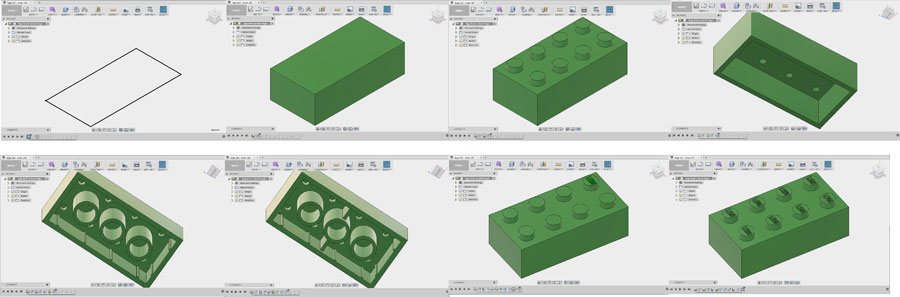
I followed up with building a "parametric lego brick" exercise to handle the parametric functionality of Fusion 360. Changing the parameters is a very good way to see mistakes in the design and it is good to do it as one goes along. It took me a while to get it right and had to redo it a few times.