Assignment:
A_ Design a board that integrates sensors to control devices
B_ Program the board to capture datas
B_ Program the board to capture datas
A_Design the board.
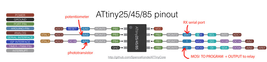
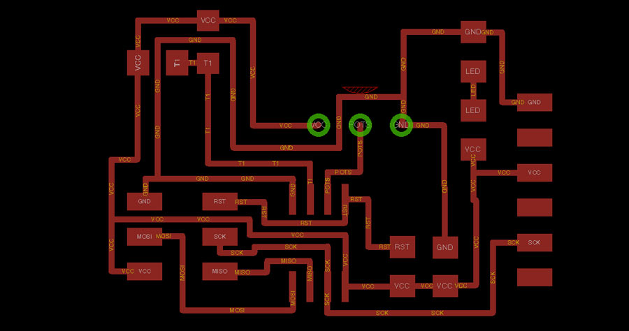
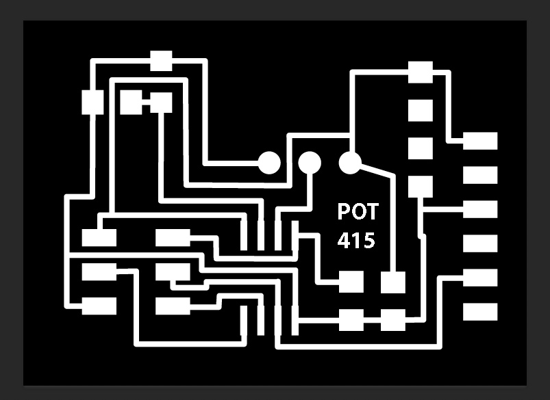
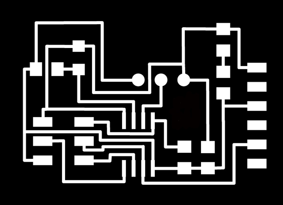
I will use the Hello.light.45 board as a template to which I will add a potentiometer connected to the free pin of the attiny45 - that is 2 inputs. And I will also add a led connected directly to current so it turns on when the board is connected.
I connected the phototransistor to PB4 and the potentiometer to PB3 so it can be placed between the sensor and the led - avoiding the led light to spill on the light sensor and influence its reading.
Also the PB0 pin of the Attiny that is used as MOSI while programming the board can be used as PIN0 for the output to trigger the relay.
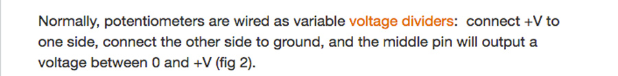
The potentiometer I found in my lab's inventory did not exist in any library that I found for Eagle so I chose a component that had the same pin size and connected the pins following these instructions:
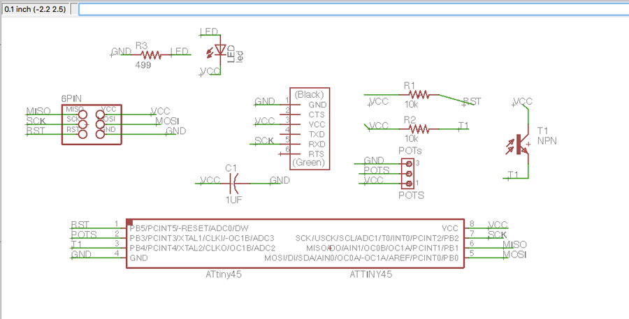
Bill of component:
(1)attiny45
(1)6pin header
(1)ftdi header
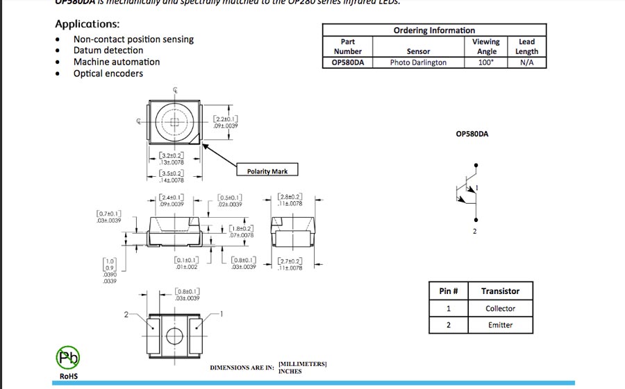
(1)phototransistor (light sensor)
(1)Resistor 10K(R1)
(1)Resistor 10K (R2)
(1)Capacitator 1Uf
(1)potentiometer (3 pins)
(1)Led
(1)resistor 499ohms
B_ Program the board to capture datas.
I first downloaded from the fab Academy page the make, C and python files to program the board and saved it on my desktop. In terminal I installed the .make file, selected the usb port and executed the python code.
The terminal commands I used to program the board and run the program are the following:
Go to the directory where the files are saved
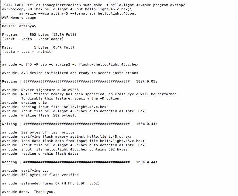
load the C code on the Attiny through either the FabIsp or the Avrdude programmer.
sudo make -f hello.light.45.make program-usbtiny
This creates a .hex file and an .out file _ making the Attiny ready to receive instructions/program, and allowing the AVRdude (or FabIsp) to program the Attiny. The message at the end should end up with: THANK YOU.
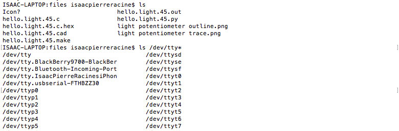
Now to execute the python code fron Terminal we need to identify the serial communication port the computer use to connect with the board.
To do that type:
ls /dev/tty*
A list of available port will come out. The one with a name that includes USB (because the FTDI cable from the board is connected to one of the computer USB port.) is the one to select. In my case it was: /dev/tty.usbserial-FTHBZZ30
type:
python hello.light.45.py /dev/tty.usbserial-FTHBZZ30
The Python interface will open a window with a graphic showing the values from the potentiometer which is on pin PB3.
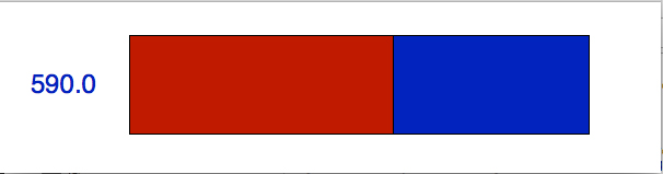
As expected the python interface read the potentiometer signal controled the graphic interface.
I tryed to get into adapting the C code so to also read the values of the light sensor but soon realized it was a very complex task for my programming skill level. Even though I did not get any result I studied the datasheet and got an idea of what I would have to reconfigure the bits of the ADC3 pin -which coresponds to PB3- by changing the register and add all the code of the light sensor on PB4/ADC4.
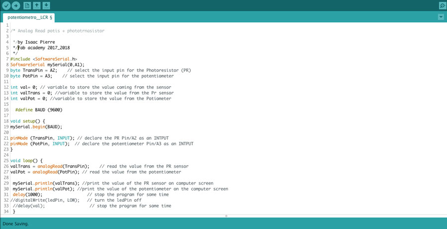
Seeing that I would not get anywhere doing it from the C code I turned to Arduino and adapted a software serial example sketch.
PB2= PIN2 (digital PWM) or A1 (analog)
PB3= PIN4 (digital PWM) or A2 (analog)
PB4= PIN3 (digital PWM) or A3 (analog)
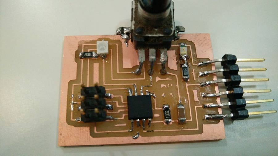
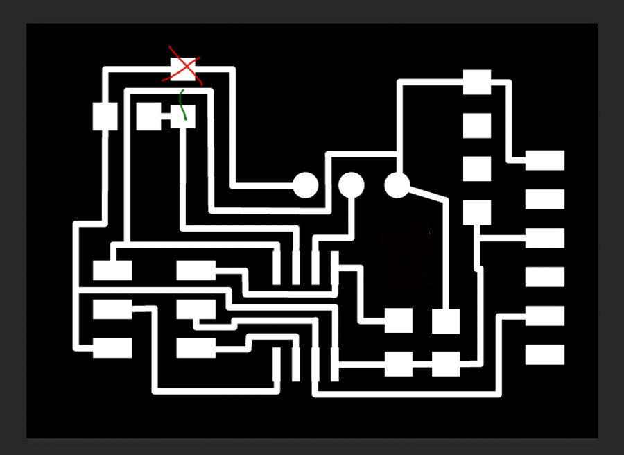
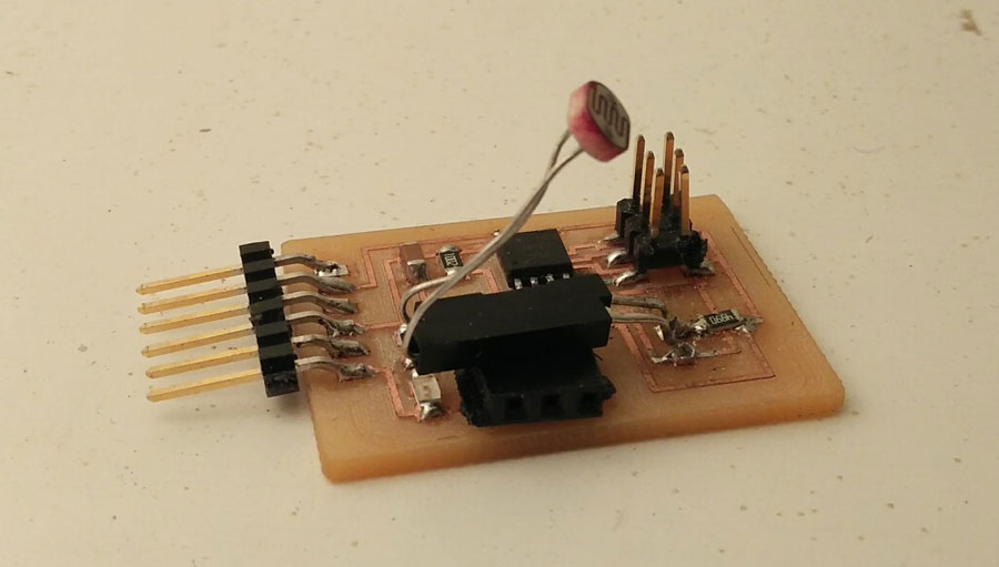
I managed to read the potentiometer values through the Attiny45 PB3 pin (Arduino A3) but I could never get a proper reading from PB4(Arduino A2). I have struggled a lot with it and realized there was a mistake on my board. The photosensor was not connected to Ground. I corrected the diagram and the board on Eagle and milled a new board. But this time instead of a potentiometer I soldered a 3 pin female so I can connect the potentiometer or other components.
The new board worked just as the previous one and I still could not get an accurate reading from the phototransitor. I studied the datasheet of the photransistor, made shure the polarity was right, replaced the resistor, by-passed the sensor to make shure current and voltage was right but all I got is erratic reading and if a change in the value it would be minimal. (for example 1023 to 1014) while the potentiometer was showing a complete range (0 to 1023)
Eventually as time was running on me I decided to replace the photoresistor by a LRD sensor and soldered it onto the trace directly and that solved the problem.With that sensor I could get a more accurate reading. Not the whole range but enough to tell my board and my code are working right. To get the complkete rabge I would have to replace the resistor for a one with the same value of the LRD sensor.
Few notes here that I learned and found very helpful: the ground (-) is the emittor. The vcc (+) is the receptor. Current travels from emitor to receptor, from - negative to positive.
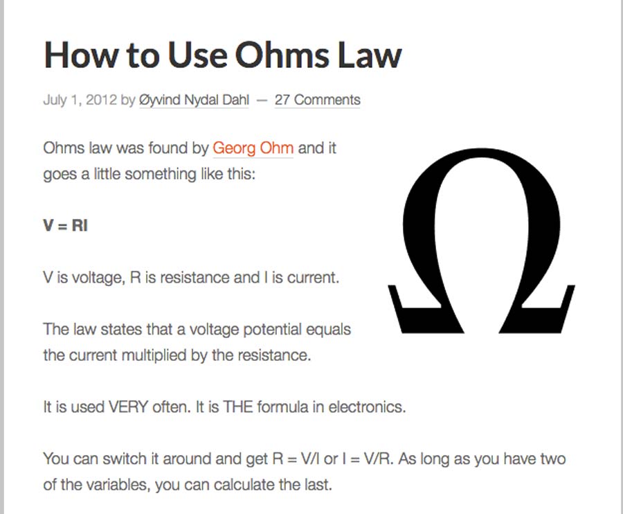
The Ohm's law
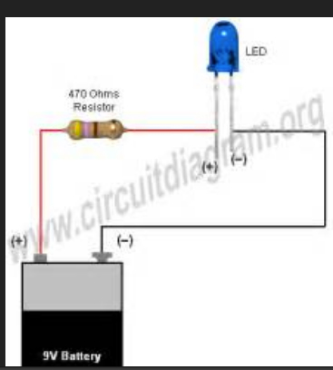
How to connect a led and its resistor.
Conclusion
With this assigment I had a great experience with the electronic part and I managed to be very efficient with designing the board (including selecting the components), mill and stuff the board. It went fast and managed the whole process without having to go through the usual endless debugging nightmare.
I need to put more effort onto programming now. C and python are still too complex but focussing on Arduino will get me to understand better the logic of coding and that will open me to assimilate easier other languages.